
Heavy-Duty Construction Equipment Floor Slat Chain Assembly Line Technical Analysis
1. Line Configuration: The “Mobile Platform” Philosophy for Heavy Machinery
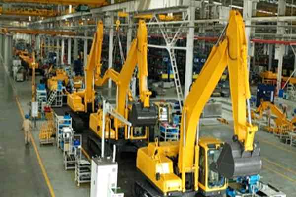
The image shows a floor‑mounted slat chain assembly line whose defining characteristic is the rejection of conventional overhead suspension or belt‑conveyor solutions in favor of a buried chain‑driven steel‑plate system that directly supports and transports complete machines between workstations. This design is a direct response to excavator product characteristics—single‑unit weights typically range from 6 to 50 metric tons, with the center of gravity concentrated in the lower crawler undercarriage, making suspended conveyance neither practical nor safe.
The yellow crawler chassis rests directly on the slat plates, whose width is matched to the crawler ground‑contact width to prevent lateral deviation during movement. Plate surfaces undergo induction hardening to achieve HRC 45+ hardness, resisting repeated compression from crawler metal grousers. Safety corridors exceeding 1.5 meters are reserved on both sides of the line to accommodate the operating radius required for heavy‑component lifting operations.
2. Plant Architecture & Logistics Hierarchy
The assembly facility employs large‑span steel‑truss structures, with column spacing significantly exceeding that of ordinary appliance or automotive plants—typically 12 to 18 meters—to provide running paths for overhead bridge cranes. Multiple bridge cranes suspended from the roof constitute the aerial logistics layer, responsible for inter‑station transfer of heavy modules including engine assemblies, swing platforms, and boom‑arm‑bucket combinations. Crane lifting capacities generally range from 10 to 50 metric tons, corresponding to finished‑machine weights.
The floor slat‑chain line forms the ground assembly layer, handling continuous flow and positioning of machine undercarriages. The lateral line‑side areas constitute the side logistics buffer layer, where hydraulic lift‑platform trucks and heavy‑duty forklifts manage replenishment of medium‑weight components such as tires, hydraulic tubing, and electrical harnesses. The three‑tier logistics system maintains clear separation of responsibilities, preventing interference between heavy lifting operations and precision assembly tasks.
3. Assembly Process Sequence: From Travel Mechanism to Working Equipment
3.1 Undercarriage Loading & Powertrain Installation
The line head receives pre‑assembled crawler undercarriages, including travel motors, drive sprockets, track rollers, carrier rollers, and track‑tensioning devices. The engine assembly is vertically lowered from above by bridge crane, mating with suspension cushions mounted on the chassis longitudinal beams. This station employs a four‑point rubber‑mounting structure, both isolating engine‑vibration transmission to the frame and permitting torsional deformation of the undercarriage under rough‑terrain conditions. Following engine placement, operators connect the drive shaft to the main pump from beneath the chassis. This workstation requires either a liftable pit or a tilting platform to enable safe access to the under‑vehicle workspace.
3.2 Swing Platform Marriage
The swing bearing (slewing ring) is pre‑installed at the chassis center position, while the swing platform (upper structure) is handled as an independent module lowered into position by bridge crane. This operation demands extremely high coaxiality—radial clearance between inner and outer races of the swing bearing is typically controlled within 0.1 to 0.3 millimeters. Initial positioning is achieved through guide taper pins, followed by hydraulic‑wrench tightening of bolts in diagonal sequence across three torque stages. Tightening torque may exceed 2000 N·m, requiring torque multipliers or electric calibrated wrenches for completion.
3.3 Hydraulic System Installation
Excavator hydraulic systems typically operate at 31 to 35 MPa working pressure; tubing leakage would directly result in operational failure. The line mid‑section features hydraulic‑tubing assembly islands, where operators retrieve high‑pressure hoses and rigid pipes of various specifications from line‑side racks, routing them along predetermined clamp paths. Tube fittings employ either 24‑degree cone‑sealing or flange‑sealing configurations. Following tightening, pressure‑retention testing is mandatory—1.5 × working pressure maintained for 10 minutes, with pressure drop not exceeding 3 % of the rated value. The hydraulic reservoir is filled during this phase, with fluid cleanliness required to meet ISO 4406 18/16/13 grade.
3.4 Working Equipment Assembly
The boom, arm, and bucket constitute the excavator’s front working equipment, interconnected through pin joints. The image shows multiple yellow booms already erected at various assembly stages. Pin bores employ clearance‑fit design, with bore‑tolerance bands controlled to H7/f7 grade to ensure field‑service disassembly capability. Following pin installation, cotter pins are inserted for axial retention, preventing end‑play displacement. Hydraulic cylinders (boom cylinder, arm cylinder, bucket cylinder) have their rod ends and barrel ends hinged to adjacent components respectively, forming a complete linkage mechanism.
3.5 Cab & Electrical Completion
The cab module is a complete drop‑in assembly, with instrument panel, seat, control joysticks, and display screens pre‑installed internally. Following placement, electrical interfaces are mated with the swing platform, including engine ECU communication lines, hydraulic pilot‑control lines, and monitoring‑camera signal lines. Harness connectors employ Deutsch or Amphenol brand products rated IP67 or above for waterproofing, addressing outdoor heavy‑rain operating conditions. The final workstation executes whole‑machine functional integration: engine idle and rated‑speed calibration, hydraulic‑action cycle testing, and swing‑brake performance verification.
4. Station Takt & Flexible Control
Heavy‑duty assembly lines do not pursue the high‑speed takt rates of appliance industries, instead emphasizing “steady‑state flow”. Typical station takt times range from 30 to 60 minutes, with slat operating speeds below 0.5 meters per minute. Starting and braking employ variable‑frequency soft acceleration/deceleration to prevent inertial‑shock‑induced machine swaying. Each station is equipped with mechanical stops and pneumatic clamping blocks—the slat stops upon arrival, clamping blocks lift to secure the undercarriage, establishing a rigid work reference.
Multi‑model coexistence is standard practice for such lines. By adjusting slat‑carrier‑unit spacing, replacing locating‑pin positions in station fixtures, and switching component‑box configurations in line‑side racks, the same line can mix‑produce 6‑ton compact excavators and 20‑ton medium excavators, with changeover completed within shift‑break intervals.
5. Inspection & Roll‑Off
The line terminus incorporates a whole‑machine performance test zone, comprising static inspection and dynamic trial‑operation phases.
- Static inspection covers hydraulic‑system sealing integrity, electrical‑system insulation resistance, and structural‑weld visual examination.
- Dynamic trial operation is conducted on a dedicated test field, simulating combined digging, swinging, and traveling motions with continuous operation for no less than 2 hours, collecting data on engine exhaust opacity, hydraulic‑oil temperature rise, and structural‑vibration acceleration.
Upon test qualification, nameplates are affixed and identification markings sprayed, with machines transferred by heavy flatbed trucks to finished‑goods yards.
Email:yu.yblsx@gmail.com