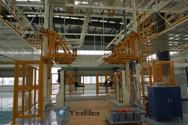
I. System Overview
This equipment is a chassis assembly and vehicle off-line inspection conveyor system for the automotive assembly line of small and medium-sized automobile manufacturers. It adopts a standard combined process layout of “overhead suspension chain transportation + floor friction conveyor (floor drag chain) + lift transfer.” The entire system uses the floor drag chain as the main conveyor line, cooperating with overhead transfer lifting platforms to achieve smooth transitions of the vehicle body between different heights and conveying forms. It covers the complete automotive assembly line process from Body-in-White (BIW) loading to final rain test inspection. The equipment features a mature and reliable structure with a wide adjustable operating rhythm, suitable for various production scales from 10,000 to 150,000 units per year, covering everything from small-batch customization to medium-scale mass production. All equipment parameters can be customized according to customer workshop conditions, vehicle model characteristics, and capacity requirements.
II. Division of Assembly Process Sections and Conveying Flow
1. Interior Pre-assembly Section (Floor Slat/Skate Line Input)
After the BIW is loaded, it first enters the interior pre-assembly section of the automotive assembly line. This section uses a floor slat conveyor or self-propelled skate, with the vehicle floor height at approximately 400–450mm above the ground, facilitating operators to enter the vehicle for assembling interior parts such as the instrument panel, wiring harnesses, carpets, HVAC units, and front wall modules. The number of workstations in this section is configured based on the assembly content and takt time requirements. A body transfer point is set at the end, where the body is lifted by a hoist into the overhead suspension conveyor and raised to approximately 1.6–1.8m above the ground to enter the chassis assembly area.
2. Chassis Final Assembly Section (Core Section of the System)
The chassis final assembly section is the core link of the automotive assembly line and the main working area of this equipment. It uses a floor friction-driven drag chain as the main conveying carrier, cooperating with an overhead transfer lifting platform to complete the lifting and positioning of the vehicle body. The specific process is as follows:
(1) Overhead Body Transfer and Lowering
The body is conveyed by the interior section’s suspension chain to above the overhead transfer lifting platform at the chassis line entrance. The heavy-duty support arms of the lifting platform rise under motor drive, supporting the side skirts or longitudinal beam reinforcement areas of the body, and decoupling from the suspension hoist. The lifting platform then carries the body down vertically to an assembly height of approximately 1.4–1.6m above the ground, leaving ample space for underbody operations.
(2) Floor Drag Chain Conveying and Station Positioning
The lifting platform smoothly places the body onto an accumulating trolley of the floor drag chain. The trolley is pulled by a floor friction drive device and slowly moves forward along the track laid in a pit. A pneumatic positioning stopper is installed at the front of each workstation. When the trolley arrives, the stopper pops out a block, disconnecting the trolley from the friction drive wheel to achieve precise positioning and stopping. The entire line running speed is 6–10m/min, lifting speed is 4–5m/min, and positioning accuracy is ±3mm. All the above parameters can be customized according to production line requirements.
(3) Chassis Major Assembly Operations
After the body is positioned, operators or auxiliary lifting equipment complete the following assemblies in sequence under the vehicle (the order can be combined or split according to the vehicle model process):
- Front suspension and subframe assembly (including steering gear and stabilizer bar pre-assembly)
- Rear axle / rear subframe assembly
- Powertrain (engine-transmission or motor-reducer) assembly
- Exhaust pipe / high-voltage wiring harness / fuel line connections
- Fuel tank / high-voltage battery pack installation and fixing
- Tire sub-assembly and on-line tightening
Each workstation is equipped with manual or electric lifting platforms. Operators use torque-controlled pneumatic/electric wrenches to tighten bolts. Tightening data can be stored locally or uploaded to the workshop management system as required.
(4) Station Release and Continuous Flow
After the operation at a single station is completed, the operator presses the release button. The positioning stopper retracts, the trolley re-engages with the friction drive wheel, and is pushed to the next workstation. If the next workstation is occupied, the trolley automatically accumulates and waits at the front stopper without pushing the preceding vehicle, achieving a flexible takt time buffer.
(5) Chassis Line End Lifting Transfer
After all chassis assembly is completed, the body reaches the end of the chassis line. A second overhead transfer lifting platform is installed here to lift the body from the floor drag chain trolley, raise it vertically, and re-hang it into the overhead suspension chain or transfer it to the floor final assembly line.
3. Final Assembly and Filling Section (Floor Slat Line)
After the body is transferred from the chassis line, it enters the final assembly section of the automotive assembly line. This section returns to floor slat conveying, with the vehicle floor approximately 750–850mm above the ground, facilitating operators to complete the following processes:
- Filling coolant, brake fluid, refrigerant, and windshield washer fluid (equipped with quantitative filling machines)
- Installing seats, seat belts, door trim panels, and sunroof interior panels
- Battery installation and wiring
- Appearance inspection, label application, and VIN engraving
The number of workstations in the final assembly section is flexibly configured according to the assembly content, matching the takt time of the chassis section.
4. Inspection Line (Wheel Alignment → Lighting/Braking → Roller Dynamometer)
After final assembly, the vehicle is driven by an operator or an automatic towing device into the inspection line, passing through in sequence:
- Wheel Alignment Station: Roller alignment equipment detects and adjusts toe, camber, and caster angles.
- Lighting Inspection Station: Automatic headlight testers check high/low beam intensity and aim.
- Brake Test Bench: Roller reaction-type brake tester measures braking force distribution.
- Roller Test Bench (Optional): Simulates road load to test speedometer, ABS activation, abnormal noises, etc.
All inspection equipment is fixed on the ground. Vehicles enter one by one, and inspection data is automatically uploaded and archived. Non-conforming items are handled at the rework station.
5. Rain Test Booth (Vehicle Sealing Inspection)
After passing the inspection line, the vehicle enters the rain test room, which is the final critical quality checkpoint before the vehicle leaves the automotive assembly line. The rain test booth is a closed steel structure channel with multiple sets of spray pipes and fan nozzles arranged inside. The specific configuration is as follows:
- Spray System: Nozzle arrays are arranged on the top, left/right sides, and front/rear ends to simulate heavy rain conditions, with spray angles covering the entire vehicle surface.
- Rainfall Standard: Spray intensity is executed according to GB/T 12480 standard or customer enterprise standards, typically 5–10mm/min, with a continuous spray time of 2–5 minutes, all customizable.
- Water Quality Requirements: Use clean circulating water, equipped with a filtration system to prevent nozzle clogging. Water temperature is close to room temperature to avoid condensation interference.
- Inspection Method: The vehicle slowly drives through the water curtain (or remains stationary). After the rain test, quality inspectors check for leaks inside the vehicle, trunk, and engine compartment. If leaks are found, they are handled at the adjacent rework station. If passed, the vehicle is released.
- Water Circulation System: A water collection tank and sedimentation filter tank are set at the bottom of the rain test booth. Water is treated and pumped back into the spray pipes for recycling.
6. Off-line Area
After passing the rain test, the vehicle drives out of the rain booth and enters the finished vehicle parking lot or debugging track waiting area. At this point, the entire automotive assembly line process is completed.
III. Key Equipment Technical Description
1. Floor Friction Conveyor System (Floor Drag Chain)
- Track Form: Heavy-duty steel plate stamped tracks laid in a pit about 250–300mm below the ground. The track surface is flush with the ground, not affecting personnel passage or forklift operations.
- Drive Method: Friction drive stations are set up in sections along the line. A geared motor drives a polyurethane friction wheel to press against the trolley’s drawbar to generate thrust. There is no rigid connection between trolleys; flexible pushing is achieved based on the accumulation principle.
- Trolley Structure: Each trolley is equipped with four heavy-duty rollers. The carrying surface is mounted with adjustable body support brackets (V-shaped locating blocks or profile fixtures), suitable for different models with a wheelbase of 2300–3100mm. The brackets can be manually or servo-electrically adjusted, and other wheelbases can also be customized.
- Accumulation Function: When the downstream is congested, trolleys automatically accumulate in front of the stopper. The drive wheel slips idly without damaging the drive mechanism.
2. Overhead Transfer Lifting Platform
- Structural Form: Double-column or four-column gantry frame, welded with H-beam steel, surface hot-dip galvanized or sprayed with anti-rust paint. The lifting platform is a box girder welded structure.
- Drive Method: Synchronous brake motor drive, ball screw or chain transmission, equipped with absolute encoder for real-time position feedback.
- Support Arm Mechanism: Retractable support arms are installed on both sides of the lifting platform, with polyurethane buffer pads and body positioning profile blocks at the ends. The arms are driven by cylinders, with a single action time of ≤4 seconds.
- Safety Protection: Equipped with anti-fall safety clamps, upper/lower limit switches, and overload sensors. The electromagnetic brake automatically locks in case of power failure.
3. Positioning Stop and Control System
- Stopper: Pneumatic stopper, cylinder-driven block lifting, response time ≤1.0 second. The block is flush with the ground when retracted.
- Control Cabinet: Floor-mounted electrical control cabinets are arranged along the line, built-in with standard industrial components such as PLC, inverter, circuit breaker, and relays. Cabinet protection class IP54.
- Operation Panel: Each workstation has a local operation box, including start, emergency stop, reset buttons, and a three-color status indicator light.
4. Safety Protection Facilities
- Fencing System: Yellow grid safety fences are installed on both sides of the entire line, 1.2–1.5m high, with safety interlock switches on the fence gates.
- Audible and Visual Alarm: When the lift and floor drag chain start or stop, the rotating warning light on top flashes with a buzzer alert.
- Cable Management: Power supply for mobile equipment uses floor cable reels, which automatically retract and release with the equipment’s lifting movement.
IV. Equipment Technical Parameters (Typical Reference Values, All Customizable)
| Item | Typical Parameter | Remarks |
|---|---|---|
| Applicable Models | Sedans, SUVs, MPVs, and new energy vehicles with a wheelbase of 2300–3100mm | Brackets can be customized for other wheelbases |
| Annual Capacity | Approx. 10,000–150,000 units | Takt time and number of stations adjusted as needed |
| Design Takt Time | 60–720 seconds/unit (adjustable) | Customized according to capacity requirements |
| Floor Drag Chain Speed | 6–10m/min | Variable frequency speed regulation, customizable |
| Lift Speed | 4–5m/min | Customizable |
| Single Unit Load Capacity | ≤2500kg | Can be increased as needed |
| Positioning Accuracy | ±3mm | Customizable |
| Power Supply | Three-phase 380V/50Hz | Voltage and frequency can be adjusted according to export country standards |
| Control Method | PLC centralized control + local operation box at each station, reserved MES communication interface | — |
| Rain Test Booth Spray Intensity | 5–10mm/min (according to GB/T 12480 or customer standards) | Customizable |
| Environmental Requirements | Indoor workshop, temperature 0℃~40℃, relative humidity ≤90% | — |
V. Applicable Scenarios
This equipment is widely applicable to passenger car final assembly workshops with an annual output of approximately 10,000–150,000 units, and is particularly suitable for the following scenarios:
- Export-oriented automobile factories (KD assembly plants or complete vehicle plants for markets such as Southeast Asia, the Middle East, and South America)
- Trial production and mass production mixed lines for new energy start-ups
- Assembly lines for special vehicles, modified vehicles, and low-speed electric vehicles
- Old plant renovation projects (the floor drag chain has a shallow pit and low requirements for plant height)
The system has a high degree of modularization. Tracks, trolleys, lifts, and rain test booths can all be non-standard customized according to the actual size of the workshop. It is a pragmatic choice for small and medium-sized automobile manufacturers to establish a standardized automotive assembly line.